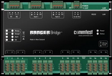
| Specifications : |
Ranger System : |
Remarks : |
| Analog Inputs |
|
|
| Number of channels |
4 to 16 |
Configurable in blocks of 4 |
| Simultaneous recordings |
Dual channel |
Any odd # channel with any even # channel |
| Channel scan rate |
≤ 8s per channel |
Acceleration 1000 Hz 400 lines |
| Compatible sensors |
Accel, Vel, Displ, Voltage Output, 4-20 mA |
|
| DC-coupled ranges |
0 V to 20 V, -10 V to 10 V, -20 V to 0 V |
Selectable to suit sensor type |
| AC-coupled ranges |
16 V peak-peak |
Allows for ± 8 V sensor output swing |
| Sensor drive current |
4 mA @ 24 V |
Enable for IEPE/ICP© type sensors |
| A to D conversion |
24-bit |
|
| Input impedance |
> 100 kΩ |
|
| Analog Measurements |
| Measurement types |
Single Value, Time Waveform, Spectrum |
|
| Quantities |
Accel, Vel, Displ, Demod, User-scaled |
User-scaling for voltage and 4-20 mA sensors |
| Max levels |
> 1000 g (10 000 m/s²), > 1000 in/s
(25 000 mm/s), > 100 in (2500 mm),
> 10 000 Amps |
|
| Spectrum Fmax values |
25 Hz to 40 kHz (1500 CPM to
2400 kCPM) |
In 26 steps |
| Sampling rates |
64 Hz to 102.4 kHz |
In 26 steps |
| Dynamic range |
≥ 95 dB |
|
| Harmonic distortion |
Less than -70 dB Typical |
Other distortions and noise are lower |
| Harmonic distortion |
± 1% (0.1 dB) |
For DC level (%F.S.) and AC measured at 100 Hz |
| AC frequency response |
± 0.1 dB from 10 Hz (AC) or 0 Hz (DC) to 15 kHz
± 3 dB from 1 Hz (AC) or 0 Hz (DC) to 40 kHz |
From value measured at 100 Hz |
| Signal Processing |
| Number of spectral lines |
400, 800, 1600, 3200, 6400 |
6400 lines (16 384 samples) max for dual channel recordings |
| Time waveform samples |
1024, 2048, 4096, 8192, 16 384 |
|
| Window types |
Hanning, Rectangular |
|
| Averaging types |
Linear, Exponential, Peak Hold, Synchronous |
|
| Number of averages |
1, 2, 4, 8, 16, 32, 64, 128 |
|
| Overlap |
0, 12.5, 25, 37.5, 50, 62.5, 75, 87.5% |
|
| Demodulation bandwidths |
24 bandwidth options |
From 125 Hz to 1250 Hz up to 16 kHz and 20 kHz |
| Order tracking |
Up to 6 kHz Fmax, Orders-based |
Tachometer required, mounted on high-speed shaft |
| Order tracking distortion |
Less than -65 dB |
Within 50% to 200% speed variation during recording |
| QuickScan Mode |
| Scan rate |
2 seconds per channel pair
5 seconds per channel pair |
For DC-coupled sensors, no integration (e.g. prox probes)
For other sensor types |
| Measurement type |
Average DC value or 10 Hz to 1 kHz overall |
Accelerometer readings are converted to velocity |
| Offline Mode |
| Storage capacity and duration |
8 MB, typically 40 days |
At 8 channels, 3 recordings per channel, 4 recordings per day |
| Recording retrieval to database |
Automatic |
Upon re-establishment of comms |
| Tachometer Inputs |
| Number |
1 to 2 |
Multiplexed, optically isolated |
| Range |
0.5 Hz to 5000 Hz (30 to 300 000 CPM) |
Divided by number of pulses per revolution |
| Recommended sensor |
Hall Effect |
Also optical, laser and Keyphasor® tachometer sensors |
| Power supply to sensor |
10 V |
Current limited to 50 mA |
| TTL inputs pulses |
2.5 V (2 mA) min, 28 V (5 mA) max |
Off-state < 0.8 V |
| Keyphasor® threshold |
13 V ± 1 V |
|
| Serial Data Inputs |
| Input type and connector |
RS232, RJ12 |
|
| Protocol supported |
MODBUS RTU |
Supports Registers (16 and 32-bit), Inputs, Coils |
| Scaling of values |
via Gain and Offset (both floating point) |
Supports all engineering units |
| Relay Outputs |
| Number and type |
1 to 2, SPST normally open |
|
| Voltage and current rating |
250 V AC or 30 V DC, 5 A |
Supports Registers (16 and 32-bit), Inputs, Coils |
| Controlled by |
OnlineManager software on server |
Supports all engineering units |
| Status Indicators |
| System status |
2 x LEDs |
One for power, one for DSP status |
| Vibration status |
2 sets LEDs: red, yellow, green |
Indicates alarm state, user-configurable |
| Relay status |
2 x LEDs |
Indicate when relays are energized |
| Communications |
| Network communications |
Ethernet v2.0, TCP/IP, 10/100baseT |
Auto-senses 10/100 Mbps and half/full duplex |
| Network connection, link speed |
RJ45 socket, ≥ 256 kbps (optimum) 2400 bps (min) |
Via any commercially available link |
| Diagnostics communications |
RS232 @ 115 kbaud, RJ12 socket |
|
| Electrical |
| Power supply |
250 mA @ 9 to 36 V |
|
| Mechanical |
| Mounting |
Standard 35 mm DIN rail |
For installation in enclosed control cabinet |
| Size |
199 mm x 130 mm x *45 mm |
*60 mm including DIN rail |
| Optional sealed housing |
IP65 / NEMA4 |
|
| Environmental |
| Temperature range |
-30 °C to 65 °C (-22 °F to 149 °F) |
De-rates to -25 °C to 60 °C (-13 °F to 140 °F) when using relays |
| Humidity |
95% RH non-condensing |
|
| Compliance |
CE, EN 61326 |
EMC emissions and immunity |

